127566, Российская Федерация, Москва, Алтуфьевское ш., д.48к3, email: info@expertnk.ru
+7(495) 660 94 49 (многоканальный номер)
8 (800) 250 94 49 (бесплатный для регионов)
+7(495) 660 94 49 (многоканальный номер)
8 (800) 250 94 49 (бесплатный для регионов)
- Certification Of Specialists
- Laboratory Accreditation
- NDT Devices & Means
- Calibration Of NDT Funds
Мера (калибровочный образец) V1
- Home
- NDT Devices & Means
- Ultrasonic method
- Calibration blocks
- Мера (калибровочный образец) V1
Price level: Retail
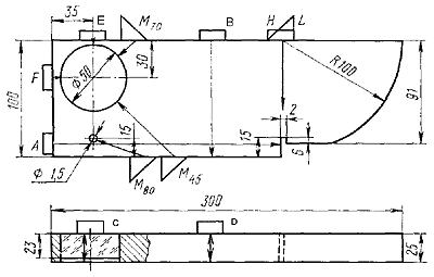
Мера (калибровочный образец) V1 - standard ultrasonic calibration samples according to ISO 7963.B.S.2704 for adjusting the sensitivity of ultrasonic instruments.
Measure V1 is used for:
- flaw detector depth gauge settings and scanning linearity check. At the same time, depending on the required sweep setting range, the direct probe is set to position A, B, C or D. The time of passage of a longitudinal wave in plexiglass (position C) corresponds to the time of passage of a distance of 50 mm over steel;
- flaw detector depth gauge settings for transverse waves. To do this, the inclined probe is set to position L and, with small movements, the maximum echo signal is obtained from a cylindrical surface with a radius of 100 mm;
- Sweep speed setting for shear waves. To do this, a direct probe is installed on a platform of 91 mm. The travel time for longitudinal waves of 91 mm corresponds to the travel time for transverse waves of 50 mm. Thus, bottom impulses are set to 50, 100, 150, etc. mm;
- determination of the exit point of ultrasonic testing and the boom of the inclined probe. To do this, the inclined probe is set to position L and, with small movements, the maximum echo signal is obtained from a cylindrical surface with a radius of 100 mm. In this position, the exit point is located in the center of the sample radius, and the arrow is counted on a millimeter scale from the exit point of the USI to the end of the transducer in the direction of sounding;
- determination of the angle of insertion of the inclined probe. To do this, the probe is set to positions M45 for entry angles of 35° ÷ 65°, M70 for entry angles of 60° ÷ 75°. With a maximum amplitude of the echo signal from the hole of 50 mm, the angle of entry is determined by the angular scales. For insertion angles of 75° ÷ 80°, the probe is set to the M80 position, and at the maximum amplitude of the echo signal from the hole Ø 1.5 mm, the insertion angle is determined on the angular scale;
- checking the minimum sounding depth, "dead" zone, straight or dual-coupled probes (probes in position F; E);
- checking the resolution of direct probes (probe in position H, Fig. V1). On the screen of the flaw detector, three pulses should be distinguishable: from the cut, from the platform at a depth of 91 mm and from the bottom surface of 100 mm;
- setting the conditional sensitivity of the flaw detector using direct probes. The converter can be installed in positions C, D;
- setting the conditional sensitivity of the flaw detector when working with an inclined probe. As a reference, echo pulses from the inner cylindrical surface with a radius of 100 mm are used; from outer cylindrical surfaces Ø 50 mm, Ø 1.5 mm. Also, a dihedral angle formed by the plane of the sample and the cylindrical surface of the hole Ø 1.5 mm is used as a reference reflector.
Package includes
- measure V1;
- the passport;
- calibration certificate;
- package.
There are no reviews for this product yet.. Write the first review.
Call us
Have questions? Call us!
+7(495) 660 94 49 (multichannel)
8 (800) 250 94 49 (free for regions)
Copyright © 2025 "EXPERT NK" LLC. All rights reserved.
| Retail | checkout at the office; |
| Online Starter* | entry level benefits; |
| Online 1..5* | five steps: more orders - more benefits; |
| Online Wholesale* | maximum benefit; |
| Online VIP* | individual discount. |
* valid only for orders placed on the site, according to the standard templates of contracts and accounts, it is mandatory to accept the Confidentiality Conditions for the information of an individual offer

